Home
Ham Story
Projects
3D Prusa Printing Freeky Wobulator Antenna Calculators Icom 7100 Raspberry Pi nanoVNA SAA2N C# code Binaural Audio Stock Retirement Analyzer Allyson Stock Trader Javascript Lessons K3NG Arduino Keyer JigSaw Generator for Laser Cutter External links
AA30-Zero SWR Maximo Robot Arm The Coolest Car Contact info
Contact

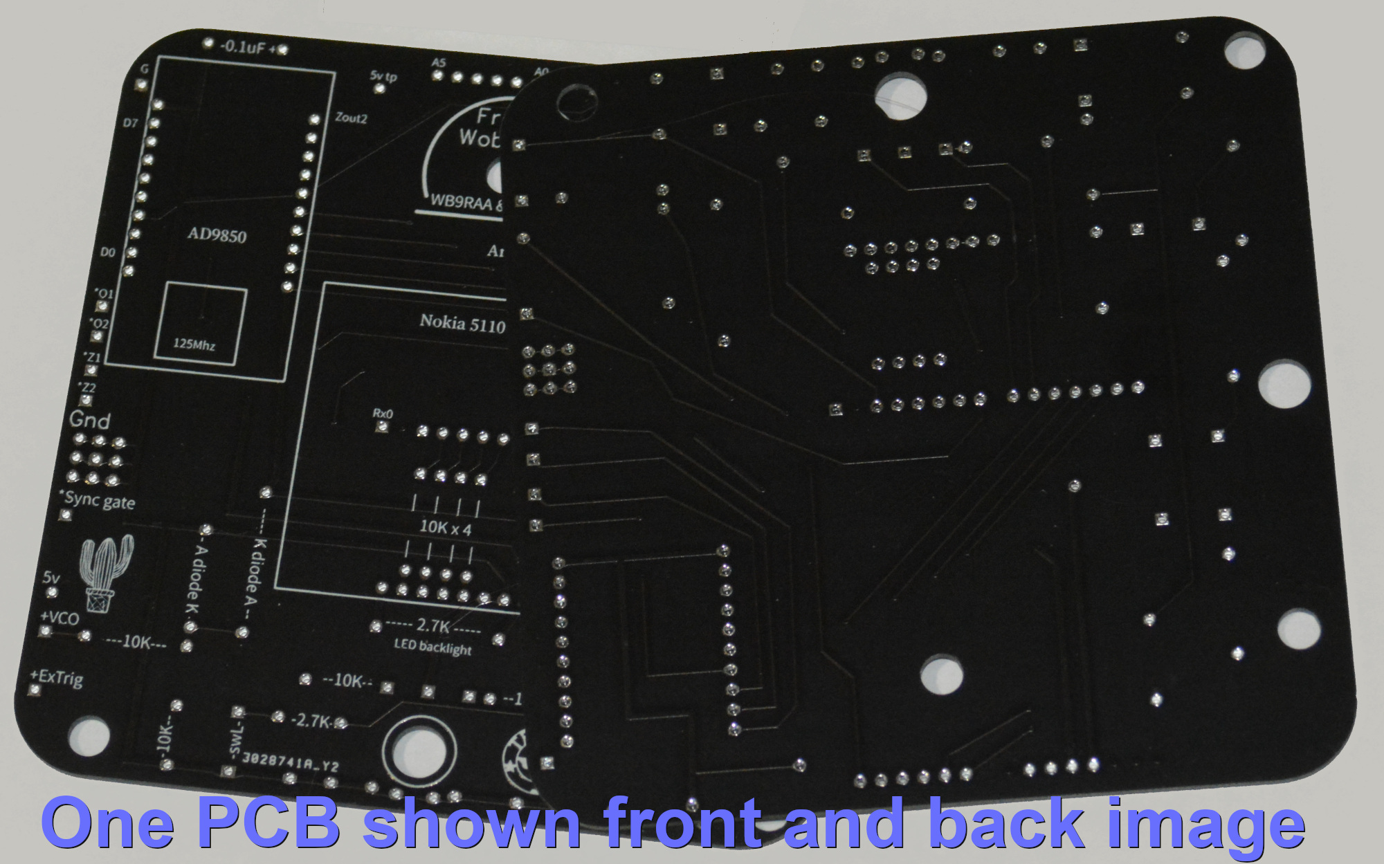
Freeky Wobulator The Arduino Function Generator
The Freeky Wobulator is a test equipment kit you can build to do a variety of interesting things. Did you ever try to build a speaker box? If so, how do you measure its performance? With the Freeky you can determine its frequency response. See if it does what it should do. You can test your entire system with the square wave function of Freeky. Are you into ham radio? Tuned circuits are a snap to measure with Freeky's programmable sweep frequency range and sweep rates. Your oscilloscope will show you exactly what the circuit is doing. The 2-tone mode of Freeky can show you how well your SSB transmitter and amplifier are performing. For the engineering folks, this little device can lead you to understand the performance of digital signal processing (DSP) and OP-amp filters. Radio alignment becomes a snap with the ability to sweep out IF bandpass or use Freeky as an RF signal generator to do a simple alignment. A VCO function allows you to control Freeky from your voltage source and play with frequency modulation (FM) experiments. Not into all that engineering stuff? Freeky can be a lot of fun too. Ever wonder how good your ears are? Freeky will tell you. Have some musical instruments that need tuning? We offer a blank Printed Circuit Board that is a oversized Arduino Shield. Add the other main parts, Nokia 5110 LCD, and AD9850 DDS board. The MIT Licensed source code is available belowSource Code Zip File
Compiled and tested under Arduino IDE 1.8.12
Specifications
Signal outputFreeky Wobulator Signal sources: 2 independent sine wave signal generators (same frequency), 1 square wave output
Sinewave frequency range: 1Hz to 42 MHz in 1Hz steps
Square wave frequency range: 1 Hz to 1.0 MHz in 1Hz steps
Sweep rate
Variable from 1 to 10 Seconds in 1 Millisecond increments
Output
Sine wave, adjustable from 0 to 2.5 V P-P,
Square wave 5.0 VP-P
Sync/Gate output for oscilloscope: 3.5-5V positive going logic
VCO input
0-5 volts
External trigger: 5V 1 millisecond pulse or greater edge triggered
Power source
5 VDC (USB) power @ 100mA (Typically 80 mA)
User Interface
84 X 48 LCD display
6 push buttons for user inputs.
(M)ode, (Z)ero (T)rigger, (S)elect, (+)Plus, (-)Minus
Encoder switch can be (S)elect or (Z)ero.
Inputs/Outputs
USB Power or Power input jack
BNC sine wave output
BNC Square wave output
USB Virtual Com port for 9600 baud serial commands
(see below)
Banana jacks
VCO input
External Trigger input
Scope trigger output
Sync Gate output
Watch video of prototype before PCB design
 Purchase PCB on
 See Bill Of Materials (BOM)
Building Freeky
Step 0 Download the Project C++ Source code and compile and download into the ArduinoSource Code Zip
Compiled and tested under Arduino IDE 1.8.12
Assembly
Step 1 Solder in the 4-10K resistors and header socket for the LCD as shown below. Solder in the 2700 back light LED resistor. Solder in headers for the LCD and Arduino UNO.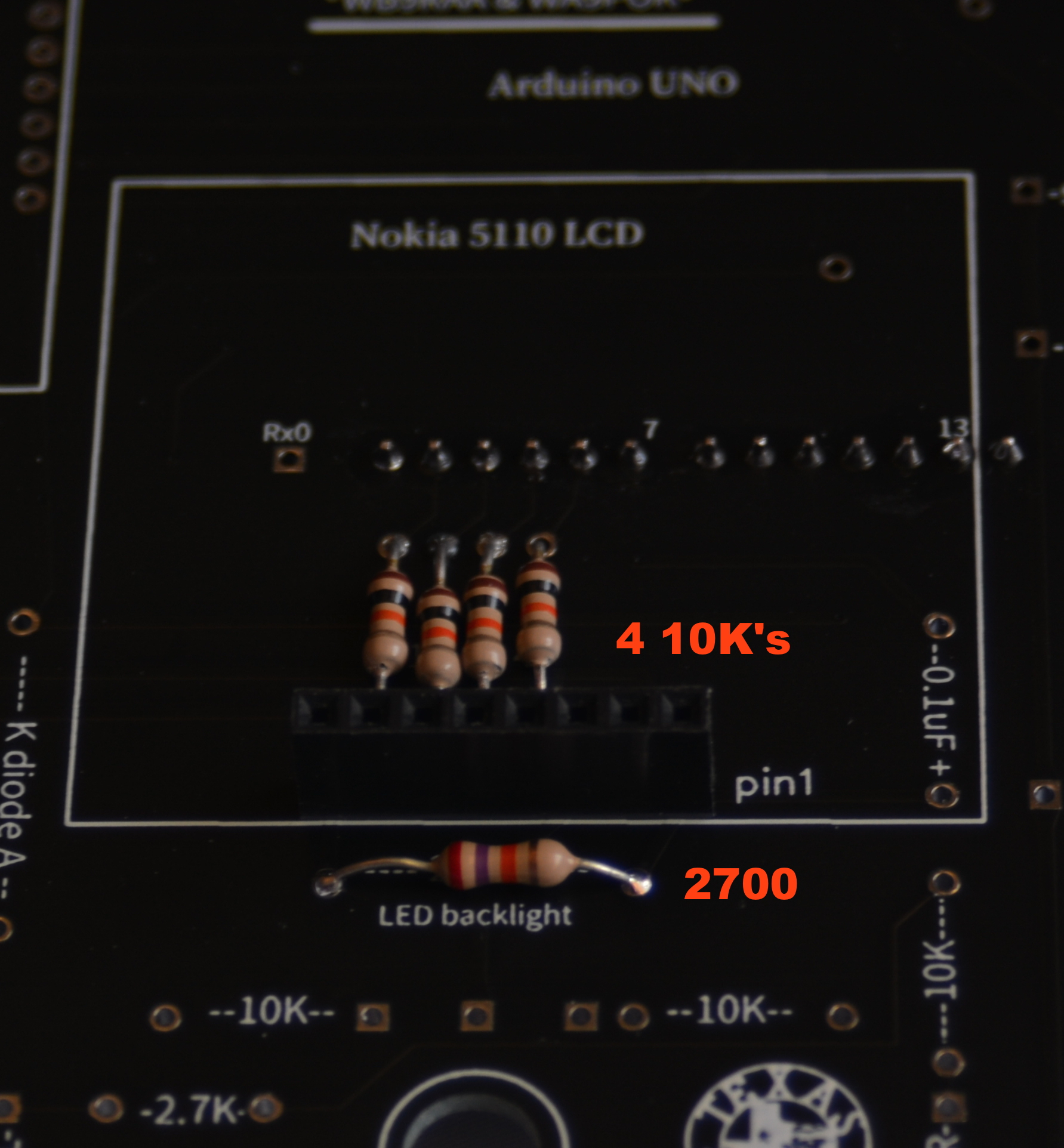
Step 2 Insert the LCD and Adruino on to the Freeky PCB as below.

Step 3 Power up the Arduino with USB power and test the LCD for the sign-on Message as below.
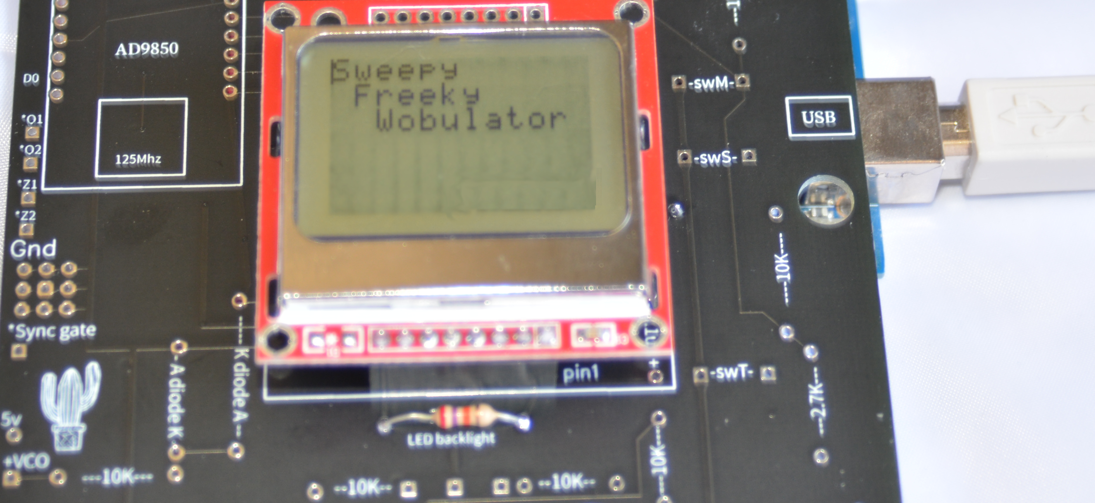
The picture above is from older firmware. The Current Firmware shows "Freeky Wobulator 9600 baud" and the version.
Step 4 Remove power and solder in the remaining parts.
See the PDF in the Doc folder of the Source code zip file and enjoy.
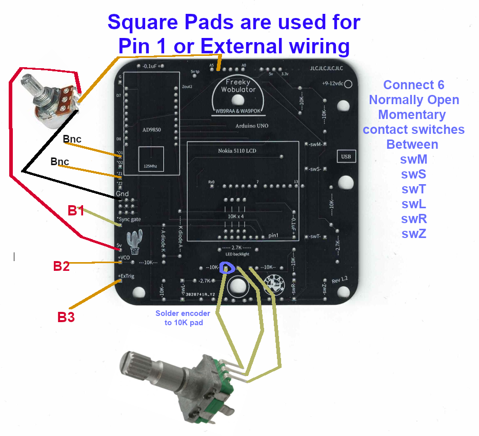
Step 5 There is a missing pad for the left encoder wire, you'll have to use the resistor pad to connect the wire. Sorry about that.
Wire the VCO Pot to A4 there is no pad since the firmware changed after the PCB was made. Analog A5 is used for the external VCO banana jack and A4 for the front panel VCO Pot. The initial design used a S.P.D.T switch to select the VCO jack or the Pot. The current design eliminates the switch and selects the jack or pot as a mode in firmware.
If your encoder has a push button switch, you can use it to SELECT, or move RIGHT, or change MODES. People have used various configurations. The encoder should increment the digits when turned clockwise. If this is not the case reverse the left and right wires.
If you choose to use an output attenuation pot wire the sinewave across the pot and ground. Connect the BNC jack to the pot wiper.
Wire up switches to the PCB pads marked swM swS swT swL swR swZ marked areas. Wire the *O1 (Square wave) to the BNC square wave output. Wire the *Z1 (Sinewave) to the BNC sinewave wave output.
Wire the B1,B2,B3 as show above to Red banana jacks. Wire the Black banana jacks to ground.
Calibration
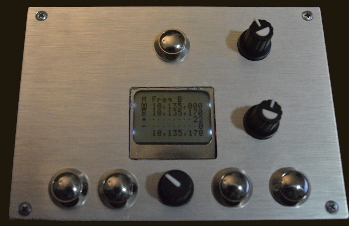
Power up, set the mode to VCOA and a Frequency to 1 Mhz and adjust the AD9850 Pot for a 50% duty cycle on the *Z1 or *Z2 square wave. Congratulation, you're done.Final Assembly All Boxed Up
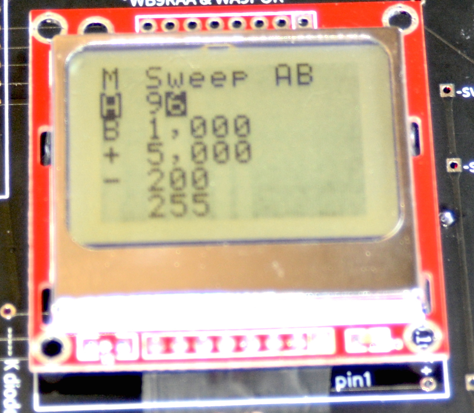
Quick Start Operation
There are six push buttons and one encoder- Mode switch selects FreqA,B,SweepA,B..Etc.
- Selects one of four lines A,B,+,-
- Left move cursor left to active digit
- Right move cursor right to active digit
- Zero digits to right of active digit
- Trigger On,Off,Rise,Fall
- EncoderChange Frequency / Time up and down at digit on cursor
- Mode 3 seconds save setting to EEPROM for next power up
- Select 3 seconds Copy other Freq or Time to Active Freq / Time Line.
- Trigger 3 seconds Swap On time with Off time
- Left 3 seconds Increase value by 10%
- Right 3 seconds Decrease value by 10%
- Zero 3 seconds Decrease value by 50%
Serial 9600 Baud Virtual Com Commands
After recording the video, I added serial commands so this can be built headless with no encoder or push buttons and be controller through the serial com port.
Note: The commands must be sent ending in a newline 0x0A \n within 1 second. You will not be able to type them you will need a line buffered terminal program or you own desktop app. i.e. SendSerialString("/m=vcoa\n"); Commands are NOT case sensitive.
?
Help Display
/V
Version of Firmware
/D
Dump all info settings
/SAVE
Save all settings to EEPROM
/M=xxx (freqa freqb sweepa sweepb fska fskb vcoa vcob vcopot rtty45)
Set the Mode same as pressing Mode switch and selecting one of the ten modes
/+=timeMS (1 .. 10,000)
Set the + ON time in milliseconds
/-=timeMS (1 .. 10000)
Set the - OFF time in milliseconds
/A=FreqHz (1 .. 42000000)
Set the A Frequency in Hertz from 1 to 42,000,000
/B=FreqHz (1 .. 42000000)
Set the B Frequency in Hertz from 1 to 42,000,000
/T=x (On Off Rise Fall)
Set Trigger to On Off Rising or Falling edge
The Four Things You Need
Some inaccuracies are with the naming of "Freeky Sweepy Wobulator" as in files and doc's and product abbreviations as FSW, and yet the pictures of LCD shows "Sweepy Freeky Wobulator" - We have used FSW and later removed "Sweepy" to shorten the name to Freeky Wobulator. They are all the same. We apologize for any confusion.